PWM signals can be generated using two different methods. The first method uses a hardware module to generate the signal. Whereas the second method relies on software and lines of code to create a PWM signal. The aim of this project is to explore the second method and generate a PWM signal using Python code. The functionality of the PWM software will be tested on a DC brushed motor and a LED.
What is PWM
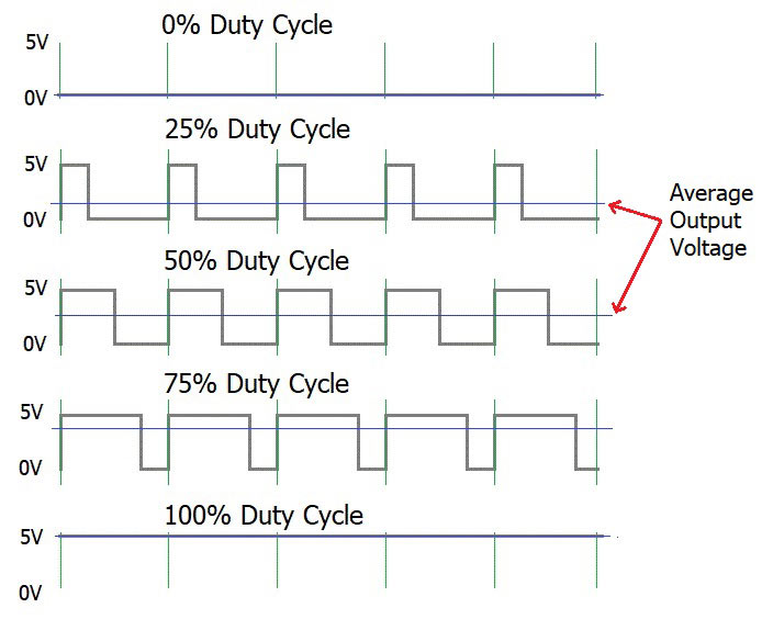
PWM stands for Pulse Width Modulation. This method is used to reduce the average power delivered to a system by cutting it into discrete values. Note that digital signals have two states ON or OFF. However, analog signals have infinitely many values. Most of the time, microcontrollers output a digital signal that is used to control a sensor or an actuator. Sometimes the actuators and sensors (DC Motors, LEDs) need an analog signal to operate. A PWM module/program is a way of controlling analog devices with a digital input signal. For example, if we send a HIGH signal to a LED light 50% of the time and send a LOW signal for another 50% of the time. The average voltage across the LED would drop to 0.5 of its actual value. Causing the LED to dim down. Figure 1 depicts a few basic PWM signals at different duty cycles.
Figure 1: PWM signals at different duty cycles
PWM Terminology
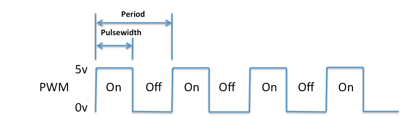
Before moving forward with the software PWM project. It is good to review some of the PWM parameters. Refer to figure 2 if you need more help.
Figure 2: Typical PWM signal with some parameters labeled
Duty Cycle: This is the amount of time the PWM signal is in the HIGH position relative to the total period of the signal. The duty cycle is usually given as a percentage and is the ratio between Ton/T of the PWM signal.
PWM Frequency: This is the number of occurrences of a repeating PWM wave. It is selected based on the system that is being controlled. for example, an LED operated by a PWM would have a frequency of 500 Hz but a small brushed DC motor would have a PWM frequency of 10 Hz.
PWM Period: This is the time it takes for one PWM wave to make a complete cycle. It is the inverse of the PWM frequency.
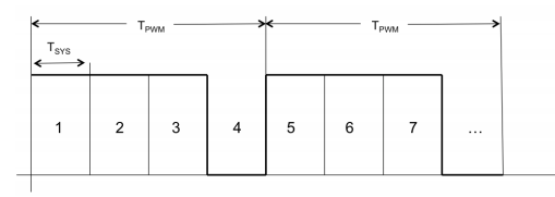
Resolution: Each period of the PWM signal is broken down into smaller segments. Each of these segments can be set to HIGH or LOW. The sum of these individual segments creates one full PWM period. The reason one might want to break the PWM period into segments is to get a better resolution. For example, if we break the PWM period into one big chunk then the duty cycle resolution would be 100% / 1. This implies that we can either have a 0% duty cycle or a 100% duty cycle. However, if we break it into 28 which is equal to 1024 parts. Then the duty cycle resolution would increase to 100% / 1024 which is equal to 0.098. This means that we can modulate the duty cycle by 0.098% when we are trying to adjust the value. Refer to figure 3 for more detail.
Step Time: This is the time interval that each small segment within a period would be on or off. Tsys in figure 3 refers to step time.
Figure 3: PWM period broken down into smaller segments for better resolution.
General Structure of a Software PWM
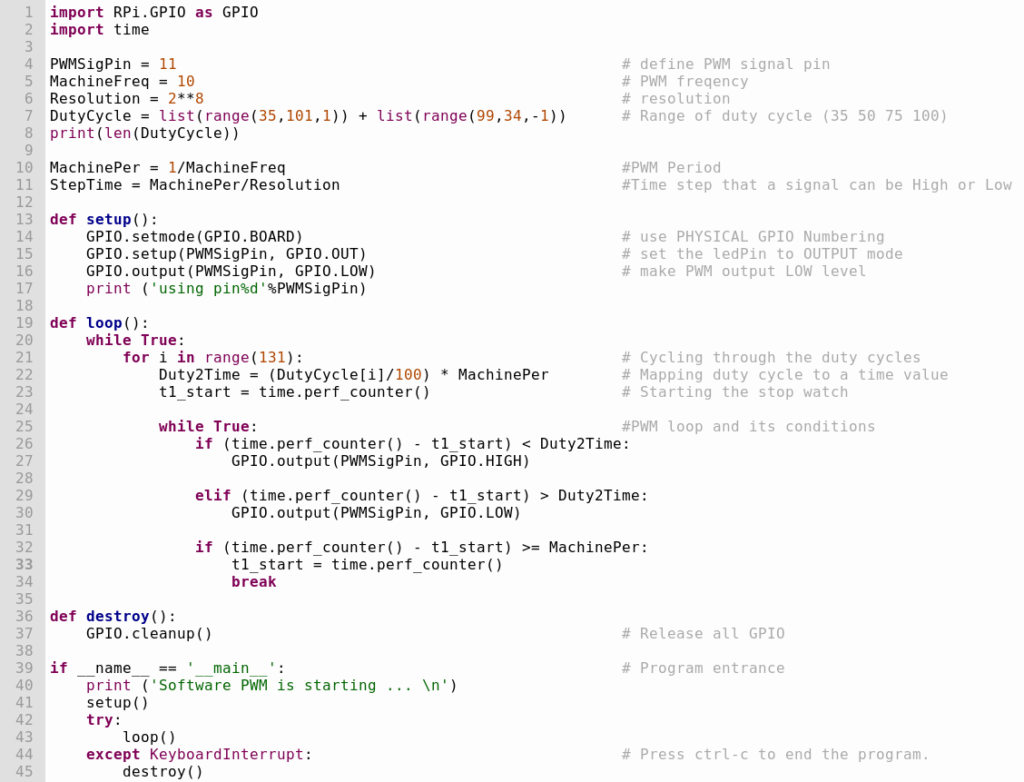
To write a software PWM we first have to define a few variables such as the duty cycle, PWM frequency, and the resolution. The second step is to create a stopwatch timer to keep track of time. Then a while loop must be created. The while loop is the PWM’s major structure. Within the while loop, three conditional statements are created and checked. The first conditional statement checks to see if the difference between the current time and the starting time (the elapsed time) is less than the time needed to get to the required duty cycle. The second condition checks to see if the difference between the current time and the starting time (the elapsed time) is more than or equal to the time needed to get to the required duty cycle. and the final statement checks to see if a full period has elapsed and resets the stopwatch. Figure 4 is a code snippet of a software PWM written in Python by me for a small DC motor.
Figure 4: Code snippet of a PWM software written in Python
DC Motor and LED Functioning Using a Software PWM
Software PWM Code
You can download the PWM code written in Python for a Raspberry Pi 4 by clicking the button below.