Navid Moghtaderi

Navid Moghtaderi
Mechanical Engineer in Training


My Works

Pick and Place Task Using UR5e Robot

Experimental and CFD Aerodynamics Analysis of FX63-137 and LRN1015

CFD & Machine Learning

Turbulent Modeling of an Airfoil 

Software PWM on Raspberry Pi 4

cycloidal drive gear reducer

Cycloidal Drive Gear Reducer

Most common gears such as spare gears have an involute tooth profile. The major problem with the involute tooth profile is that it has a lot of backlash. This is not a good characteristic when making high-precision robots. The Cycloidal reducer has near zero backlash and are a good replacement for many robotic applications. In this project, we will focus on creating a 3D model of a single-stage, double-rotor cycloidal driver using SOLIDWORKS.  

Figure 1: Exploded view of the cycloidal reducer

Parts of a Cycloidal Gear Reducer

A single-stage cycloidal drive has 6 main parts. These parts are listed below and are shown in figures 2 through 7:

Housing: This is usually a hollow cylinder where the rotor and other parts are placed inside. Moreover, the housing has mounting holes that can be used to mount the gearbox to a frame.

Rotor: This is the most important part of the gearbox. It rotates and moves on an eccentric shaft and its outer profile is constructed using an epicycloid.

Housing Rollers: These are rollers that are inserted into the edge of the housing and are in contact with the rotor. The rotor and the rollers act like a cam and follower and are always in contact. 

Output Disk: This part acts as an output shaft. The motion of the rotors is transferred to the output disk through the output rollers.

Output Rollers: These are rollers that are inserted into the edge of the output disk and are in contact with the inside of the rotors. The rotors and the rollers are always in contact and the rotary motion of the rotors is transferred to the output disk through the output rollers. 

Eccentric Input Shaft: This part acts as the input shaft of the gearbox and the rotors are mounted on it. However, the rotors are placed on the eccentric part of the shaft and can wobble as they rotate. 

Figure 2: Housing
Figure 3: Rotor
Figure 4: Housing roller
Figure 5: Output disk
Figure 6: Output roller
Figure 7: Eccentric input shaft

Design Parameters

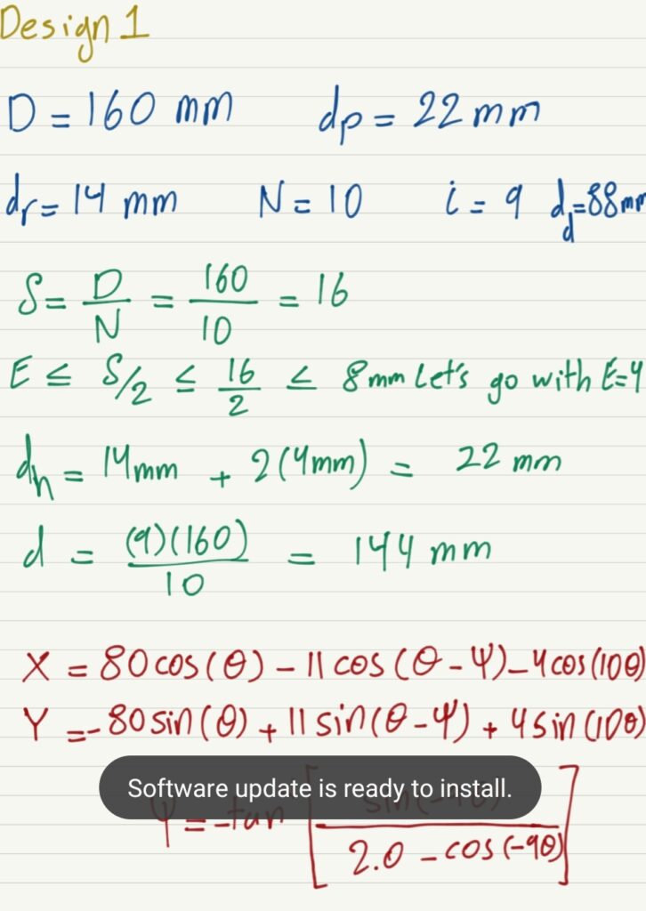
To design a cycloidal driver one must know a few important parameters such as the transmission ratio, the base circle diameter, the eccentricity, and the parametric equations that give the rotor its unique shape. Refer to figure 8 and 9 to see the selected design parameters for my design. 

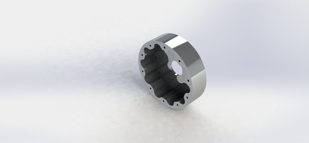
To create the unique rotor shape one can use the parametric equations listed below. Note that the parametric equations can be entered in SOLIDWORKS manually. Open a sketch then select the spline tool. Under the spline tool drop-down menu select Equation Driven Curve. In the Property Manager Select the Parametric equation and enter the equations listed below.    

X(Θ, ψ) = Rcos(Θ) – Rrcos(Θ – ψ) – Ecos(NΘ)

Y(Θ, ψ) = -Rsin(Θ) + RrSin(Θ – ψ) + Esin(NΘ)

ψ = -tan-1[(sin(1-N)Θ) / ((R/(EN)) – cos(1-N)Θ)]    for  0 ≤ Θ ≤ 360

where:

R = Base circle of housing rollers radius

Rr = Housing roller radius

E = Eccentricity

N = Number of housing rollers

The next most important task is to find the transmission ratio of the gearbox. Note that the transmission ratio is purely related to the number of housing rollers and the number of lobes on the rotor. The transmission ratio has nothing to do with the size of the gearbox and can be calculated using the following equation.

i = n / (N – n)

where:

N = Number of housing rollers

n = Number of lobes on a rotor

The base circle diameter can be calculated using the following equation:

d = iD/N

Where:

D = pitch circle diameter of the housing rollers 

The eccentricity is calculated based on the equation below:

E ≤ δ/2

Where:

δ = D/N

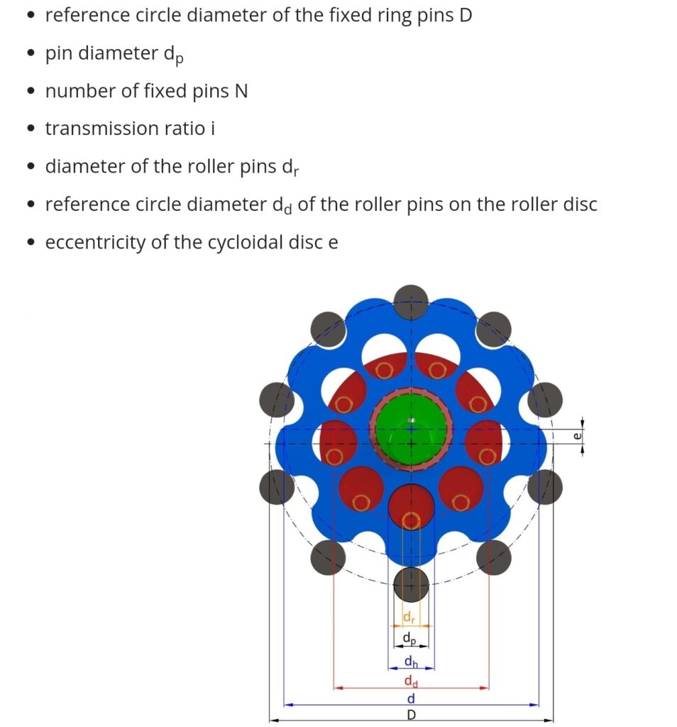
Finally, the rotor output hole diameter is calculated using the following equation:

dh = dr + 2E

Where:

dh = Rotor output hole diameter
dr = Output roller diameter

Figure 8: Selected design parameters for my cycloidal driver
Figure 9: Figure showing all the design variables and dimensions

Benefits of a Cycloidal Driver

  1. Backlash-free for a lifetime
  2. Robust design 
  3. Longer life
  4. More Compact

SOLIDWORKS Files

All SOLIDWORKS files can be downloaded at Thangs.com. Please note that the parts were designed with SOLIDWORKS 2017, so they may not work in newer models of SOLIDWORKS